
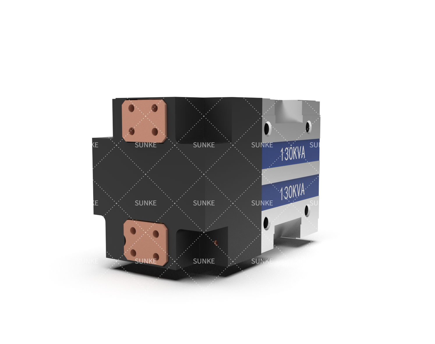
The choice of transformer technology affects more than the electrical characteristics of a welding machine. It influences cycle consistency, energy delivery, thermal management, equipment size, and the maintenance requirements of a production line.
A spot welding transformer must match the material, joint geometry, and operating frequency of its application, while alternatives such as medium-frequency DC systems and capacitor-discharge equipment serve different process needs. Understanding these differences helps manufacturing engineers assess equipment based on real production conditions rather than headline specifications.
Comparing Transformer Technologies
Conventional AC transformers operate at the supply frequency and deliver alternating current to the welding circuit. Their relatively straightforward architecture can make them suitable for established spot-welding applications, including sheet-metal fabrication and general industrial assembly. Performance depends on transformer capacity, electrical supply conditions, electrode force, and the welding schedule.
Medium-frequency DC systems use a rectifier to convert transformer output into direct current. Operating at a higher frequency allows the transformer to be designed differently from a conventional line-frequency unit, often reducing its size for a comparable application. The resulting current characteristics can suit automated manufacturing processes that require controlled energy delivery and repeatable welding cycles.
A resistance welding transformer should be evaluated as part of the complete electrical system rather than as an isolated component. The controller, rectifier, cables, welding gun, and transformer all influence the energy reaching the joint. Comparing technologies on an equivalent application basis provides a more useful assessment than relying on nominal power ratings alone.
Since transformer selection is closely related to the overall welding power and control architecture, engineers can also review the differences between MFDC, MFAC, and capacitor discharge welding controllers when evaluating alternative resistance welding system configurations.
Output Characteristics and Weld Quality
Weld quality depends on how effectively current generates heat at the interface between the materials. Current magnitude, resistance, and welding duration interact to determine the thermal energy produced. Variations in electrode condition, surface coatings, material thickness, or clamping force can change the process even when the electrical settings remain constant.
Medium-frequency DC equipment can offer useful control over current delivery in automated production. Its characteristics may benefit applications involving demanding cycle requirements or materials that require carefully managed heating. Nevertheless, DC operation does not automatically produce stronger welds; the process window must still be established through testing and appropriate quality checks.
Capacitor-discharge systems follow a different approach by storing electrical energy in capacitors and releasing it in a controlled pulse. This method can suit applications involving short-duration energy delivery, small components, or localized joining requirements. Its suitability depends on the required pulse characteristics, workpiece geometry, and material combination rather than on the technology label alone.
Energy Efficiency, Duty Cycle and Maintenance
Energy consumption should be assessed across the entire welding installation. Transformer losses, rectification, cooling equipment, cable resistance, and idle periods all contribute to operating costs. Production volume also matters: a system optimized for intermittent operation may perform differently from one expected to sustain frequent cycles throughout a shift.
Duty cycle describes the proportion of time equipment can operate under specified conditions without exceeding its thermal limits. A transformer rated for a lower duty cycle may be suitable for intermittent welding, while high-throughput applications demand careful assessment of thermal capacity and cooling arrangements. Manufacturers should review the rating conditions instead of assuming that two transformers with similar power ratings can support identical workloads.
Maintenance requirements also vary with system architecture. Conventional equipment may have fewer power-conversion stages, while medium-frequency systems include electronic components that require appropriate inspection and servicing. Cooling circuits, electrical connections, insulation, and controller diagnostics should all be included in preventive-maintenance plans to reduce avoidable production interruptions.
Application Matching and Equipment Selection
Automotive body assembly commonly relies on repeated spot welds across sheet-metal structures, making cycle consistency and integration with robotic equipment important selection factors. Battery manufacturing introduces different constraints, including heat-sensitive components, conductive materials, and precise joint requirements. Electronics and general industrial applications may place greater emphasis on small weld areas, short pulses, or compact equipment arrangements.
For medium-frequency applications, Sunke‘s MFDC transformer range lists duty-cycle options of 20% and 50%. These ratings provide a starting point for evaluating thermal suitability, but the correct choice depends on the required welding current, cycle pattern, cooling method, and installation conditions. Engineers should confirm the specific model’s full electrical specifications and validate performance under representative production loads before finalizing the equipment configuration.
Procurement teams can compare suppliers by requesting documented ratings, connection drawings, cooling requirements, service information, and evidence of application testing. Integrators should also check controller compatibility, installation space, and the effect of any replacement on existing automation. Such checks help identify hidden modification costs before equipment reaches the factory floor.
Conclusion
No single transformer technology suits every resistance-welding task. Conventional AC designs, medium-frequency DC systems, and capacitor-discharge equipment each have distinct electrical characteristics and operating considerations. A spot welding transformer should be selected according to the required weld profile, production rhythm, thermal limits, and integration needs, with testing used to verify the result. Careful comparison of the complete system gives manufacturers a stronger technical basis for balancing weld consistency, operating costs, and long-term maintainability.
