
Optical phase is not visible on a power meter, yet it carries useful information and controls how waves interfere. They use phase modulation to generate sidebands, distribute microwave signals, implement sensing methods, shift frequency, and prepare signals for coherent processing.
The device changes phase directly while preferably leaving average optical power largely unchanged. This distinction separates phase modulation from direct intensity control, although an interferometer can later convert phase differences into power variation.
Because the output is often interpreted through another optical element or receiver, the modulator must be selected as part of a chain. Bandwidth, voltage, loss, RF power handling, wavelength, and stability all influence the final measurement.
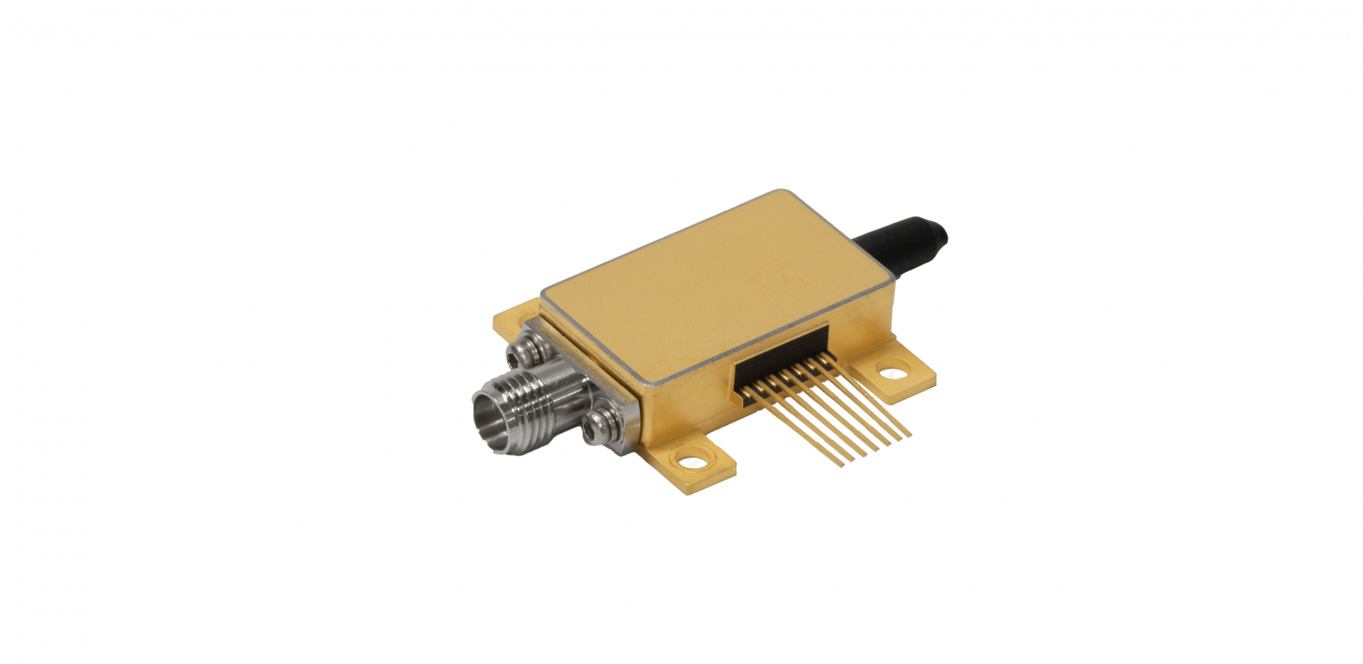
Published TFLN Devices include a 20/40 GHz phase product specified at 40 GHz bandwidth, insertion loss below 3.5 dB, half-wave voltage below 3.5 V, and a rated RF input limit of 33 dBm. They use these figures to frame qualification, while application-specific testing establishes modulation index, spectral quality, and long-term operating margin.
Phase Control Enables Functions Beyond Simple Power Switching
A phase modulator applies an electrical field to change the refractive index experienced by light. The resulting phase shift follows the drive waveform, creating frequency sidebands or time-dependent phase patterns.
In microwave photonics, this can transfer high-frequency information to an optical carrier for distribution and processing with lower transmission loss than a comparable electrical path.
TFLN devices may also support interferometric sensing, where small path-length or environmental changes are recovered through phase. The modulator can provide a known carrier, dither, or calibration waveform.
For these systems, phase noise and drift can be as important as bandwidth. They define how the modulation interacts with the interferometer and demodulation algorithm before choosing hardware. Frequency-comb and spectral-synthesis setups commonly use phase stages because strong periodic modulation creates multiple sidebands.
The useful result depends on drive amplitude, RF phase noise, optical input, and cascading. They calculate the target modulation index and line structure, then verify whether the available electrical amplifier can deliver it without compression, overheating, or excessive distortion.
Selection Requires Compatible Optical, RF, and Environmental Limits
Bandwidth must cover the upper significant portion of the drive waveform with adequate amplitude and phase response. A 40 GHz rating can support many microwave-photonic and sensing tasks, but the exact response near the operating frequency should be measured.
For a phase modulator, group delay and ripple may affect waveform reconstruction even when the nominal amplitude response appears acceptable. Keeping insertion loss below 3.5 dB helps preserve optical power for later filters, interferometers, or detectors. When considering TFLN devices, they add connector, splice, and aging allowances and confirm whether the stated value includes pigtails.
Optical-power handling is reviewed separately, because a low-loss device may still have limits that constrain a high-power experiment or transmitter. A half-wave-voltage limit below 3.5 V describes electro-optic efficiency under defined conditions, while the 33 dBm rated RF input limit establishes a stress boundary.
They distinguish normal operating power from the rated power limit and include mismatch, amplifier overshoot, and continuous-duty heating. Connector type, impedance, cable loss, and termination all affect the voltage actually reaching the electrodes.
Qualification Should Reproduce the Intended Measurement or Link
Qualification begins with the optical wavelength, polarization, temperature range, and modulation frequencies expected in service. They measure sideband ratios, residual amplitude modulation, insertion loss, and phase response using the planned RF chain. TFLN devices should also be checked for bias-free or bias-dependent behavior according to the circuit, since control assumptions can alter system complexity.
A phase modulator used in sensing may need long-duration stability tests, whereas a development laboratory may value connector flexibility and rapid reconfiguration. They tailor vibration, thermal cycling, humidity, and power-on testing to the actual environment.
The test plan should distinguish reversible temperature behavior from permanent shift and record enough data for later failure analysis. Supplier evaluation includes calibration records, serial traceability, handling limits, repair policy, and process-change notification.
They ask whether replacement units can be used with the same RF and optical settings or require fresh characterization. For volume instruments, interchangeability reduces service time; for specialized research systems, detailed individual data may be more useful than narrow unit-to-unit limits. Residual amplitude modulation deserves separate attention.
A nominal phase-device can produce small power changes through polarization effects, reflections, or electrode imbalance. In precision systems, they measure that behavior over frequency and temperature and decide whether optical filtering, calibration, or a tighter component limit is justified.
Phase modulation is useful because it gives them controlled access to an optical variable that underlies interference, coherent detection, and frequency-domain processing. Its invisible nature makes disciplined measurement especially important. A power reading alone cannot confirm that the intended phase waveform has been produced with acceptable noise and spectral purity.
They select the device by tracing the application backward from the recovered signal. That exercise identifies necessary modulation index, frequency response, loss, power handling, phase noise, and environmental stability. It also clarifies which limits belong in a purchasing specification and which should remain system-level responsibilities shared with the laser, RF source, and receiver.
Phase-modulator data become meaningful when the RF path, optical reference, temperature, and calibration method match the intended instrument. Trials of a Liobate package can then connect spectral behavior and drift directly to the sensing or microwave-photonic use case.
