
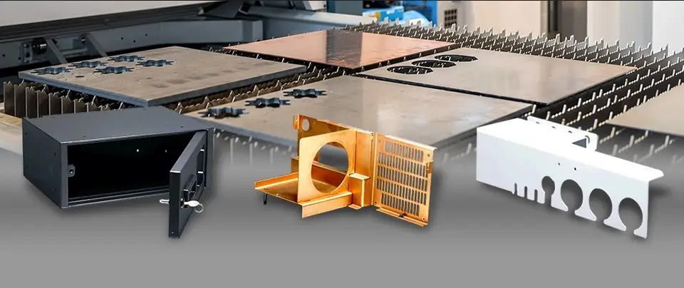
Electronic equipment can contain highly sophisticated circuits, yet the mechanical parts surrounding those circuits are often built from relatively thin metal. Their job is deceptively demanding. An enclosure may need to protect a PCB, maintain connector alignment, dissipate heat, support fasteners, and contribute to electromagnetic shielding at the same time.
That is why precision sheet metal for electronics should not be judged by one tolerance value. The more useful question is whether the fabricated component maintains the interfaces and functions that the electronic assembly depends on.
Precision Starts Where Metal Meets Electronics
A sheet metal panel rarely operates alone. It interacts with circuit boards, connectors, displays, fans, power supplies, fasteners, cables, and neighboring panels. A small positional error can therefore become significant when several components must align simultaneously.
The supplied HordRT guide identifies enclosures, chassis, frames, brackets, and other structural components as common sheet metal products used in electronic systems. It also emphasizes dimensional accuracy for alignment with PCBs and connectors.
That makes interface geometry a better starting point than simply asking for “tight tolerances.” Mounting holes, slots, cutouts, tabs, and locating features determine how the fabricated part interacts with the rest of the assembly.
A drawing that specifies every dimension equally may therefore miss the real priority. Some features control assembly; others have considerably more dimensional freedom.
A Hole Pattern Can Matter More Than the Overall Shape
Electronic sheet metal components frequently contain numerous openings. Some accommodate connectors or cables, while others locate boards, attach brackets, or provide ventilation.
Their positional relationships can be more important than the outer dimensions of the panel. A connector cutout that is slightly misplaced may interfere with an external interface even when the enclosure itself appears dimensionally correct.
The same issue can occur with PCB mounting points. A board may contain several fixed mounting locations, creating an accumulated alignment requirement between the sheet metal and the electronics.
Designers should therefore identify functional datums and critical interfaces early. Hole-to-hole relationships, connector openings, mounting surfaces, and locating features deserve more attention than cosmetic edges that have no assembly function.
HordRT’s reference specifically identifies tolerance control as a DFM consideration for electronics because fabricated parts must align with PCBs and connectors.
Thin Metal Has to Perform Several Jobs at Once
Electronic sheet metal rarely exists purely to provide a protective shell. Depending on the product, the same component can contribute structural support, thermal management, shielding, and environmental protection.
Aluminum, for example, is identified in the supplied reference as lightweight, corrosion-resistant, and thermally conductive, making it suitable for enclosures and heat-management components. Copper offers particularly high electrical conductivity and can be used in applications involving EMI shielding and thermal management. Stainless steel provides strength and corrosion resistance for more demanding environments.
Material selection consequently needs to begin with the part’s job rather than its appearance.
Ventilation introduces another design relationship. Openings can improve airflow but also remove material from a panel that may need to remain rigid. A perforated area therefore has to satisfy both thermal and mechanical requirements.
The same principle applies to electromagnetic compatibility. An enclosure may need conductive continuity across selected areas while still accommodating fasteners, seams, coatings, and access openings.
Forming Changes the Geometry You Started With
Flat-sheet geometry is only the starting point for many electronic components. Bending converts that flat blank into a three-dimensional structure, and the resulting dimensions depend on the forming operation and material behavior.
A panel may contain several bends that establish the final position of mounting surfaces and connectors. If those bends shift the relationship between surfaces, the resulting error can propagate into the assembled electronics.
HordRT identifies CNC press-brake bending as a fabrication technique used to create consistent angles and folds in electronic enclosures and structural components.
Bend sequence also matters from a manufacturability standpoint. Closely spaced features, insufficient clearance around bends, or poorly positioned holes can complicate fabrication even if the flat pattern appears correct.
For electronics high precision sheet metal parts, DFM should therefore consider the component in both states: before forming and after forming. A manufacturable flat pattern is not enough if the finished three-dimensional component cannot maintain the required interfaces.
Surface Treatment Is Part of the Functional Design
Finishing is sometimes treated as the final cosmetic operation. Electronic sheet metal can require a more deliberate approach because the surface condition may influence corrosion resistance, appearance, durability, and electrical behavior.
The supplied HordRT guide lists powder coating, anodizing, plating, and painting among the available surface-treatment approaches. It also notes that electroplating can improve EMI shielding.
A coating can, however, change the physical condition of a surface. Areas intended for electrical contact, grounding, or conductive continuity may need different treatment from exposed cosmetic surfaces.
That means finishing requirements should appear in the engineering specification rather than being added after fabrication decisions have already been made.
Color and appearance remain relevant for consumer electronics, but functional surfaces should take priority where electrical or assembly requirements are involved.
Inspect the Features That Control Assembly
Inspection becomes more effective when it follows the component’s functional hierarchy.
A quality plan for an electronic chassis, for example, should distinguish between critical mounting locations and non-critical exterior dimensions. Connector openings, PCB mounting points, bend-related interfaces, and fastening features may warrant tighter control than surfaces whose primary purpose is visual.
Fabrication technology also affects how those features are produced. The supplied reference identifies laser cutting for detailed sheet profiles, CNC punching for repeated openings and patterns, CNC bending for formed geometry, and welding or spot welding for permanent joints.
Each operation introduces its own dimensional relationships. Inspection should therefore examine the completed component, not merely verify the accuracy of the initial laser-cut blank.
Assemblies deserve attention as well. A component can pass individual dimensional checks yet create an interference condition after several parts are combined. First-article assembly checks can reveal this type of problem earlier than relying exclusively on isolated measurements.
Precision Is a System Property
High-precision electronics sheet metal is ultimately less about making every dimension extremely tight and more about controlling the dimensions that determine how the component functions inside the electronic assembly.
A successful design connects material selection, cut geometry, bend strategy, joining method, surface treatment, and inspection around the same functional requirements. The supplied HordRT guide similarly links electronic sheet metal design with tolerance control, thermal management, assembly efficiency, EMI shielding, and material selection.
That approach also prevents over-specification. Applying unnecessarily tight tolerances to every feature can increase manufacturing difficulty without improving the finished product.
The better objective is selective precision: identify the interfaces that control electrical and mechanical integration, design the fabrication sequence around them, and inspect those features accordingly. For electronics manufacturers, that is what turns a fabricated metal panel into a dependable component of the larger system.
